Sheet metal fabrication is the set of manufacturing processes that transform flat metal sheet stock into finished structural or functional components. For engineers specifying custom metal parts, procurement managers sourcing fabrication services, and product teams developing new assemblies, understanding how the full fabrication sequence works — what each process step does, in what order, and why — is essential for writing accurate specifications, evaluating supplier capability, and avoiding costly design-for-manufacturability problems late in the development cycle.
This guide walks through the complete sheet metal fabrication process in sequence, from raw material to finished component, explaining what each stage achieves and how the choice of equipment and process parameters at each step affects the final part quality.
Sheet metal fabrication encompasses all the cutting, forming, joining, and finishing operations applied to metal sheet — typically steel, stainless steel, aluminum, copper, or galvanized steel — to produce parts and assemblies. Sheet metal is defined by its thickness: generally 0.5mm to 6mm for most fabricated components, though some structural applications use thicker plate, and some precision electronics applications use thinner foil-gauge material.
The distinction between sheet metal fabrication and machining is important for sourcing decisions: machining removes material from a solid billet by cutting, while sheet metal fabrication primarily works by cutting, bending, and joining flat sheet. Sheet metal is typically faster, more material-efficient, and lower cost than machining for structural enclosures, brackets, panels, frames, and housing components. Machining is the appropriate process for precision solid parts — shafts, housings, complex 3D geometries — that cannot be formed from flat sheet.
The fabrication process typically begins with laser cutting: producing the flat 2D blank that will be further processed in subsequent stages. A CNC laser cutting machine directs a high-power laser beam — typically a fiber laser at 2,000–20,000W for metal cutting — onto the sheet surface, melting and vaporizing the material along the programmed cut path while an assist gas (nitrogen or oxygen) blows the molten material clear of the kerf.
Fiber laser cutting offers several performance characteristics that have made it the dominant cutting technology in modern sheet metal fabrication. Cut-edge quality on mild steel and stainless steel is typically smooth enough to require no secondary finishing for most applications. Cutting speed is significantly faster than plasma cutting, particularly on thinner material. And the narrow kerf width — typically 0.1–0.3mm depending on material thickness and laser power — maximizes material utilization and allows fine features (slots, holes, tabs) to be cut cleanly in a single operation.
The laser cutting stage is also where tabs, slots, and locating features for subsequent bending and assembly are cut into the blank. Designing these features correctly at the laser programming stage simplifies all downstream operations and reduces assembly time significantly — a well-designed flat blank with accurate locating slots assembles itself during welding, eliminating the need for jigs in many cases.
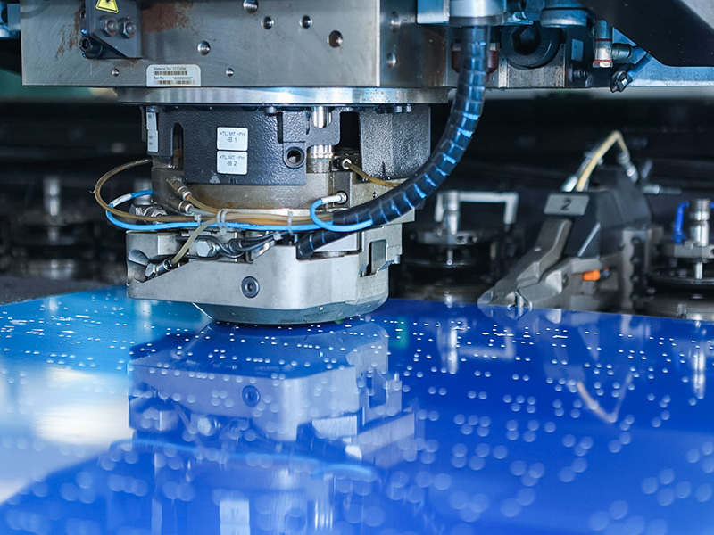
For components requiring large numbers of identical holes, slots, louvres, or embossed forms across a sheet, CNC punch press processing offers speed advantages over laser cutting for these specific features. A punch press uses a hardened tool (punch) forced through the sheet into a matching die to shear a clean hole or form in a single stroke. Modern CNC turret punch presses carry multiple tools in a rotating turret and can execute complex hole patterns and formed features at high speed — 300–600 strokes per minute for standard punching operations.
Punch press processing is particularly advantageous for sheet metal components that require ventilation louvres, extruded holes for thread tapping, embossed stiffening ribs, or countersunk hole forms — features that laser cutting cannot produce because they require material deformation rather than material removal. In many fabrication workflows, laser cutting and punch press processing are complementary: laser cutting handles complex external profiles and fine internal features, while punch press handles repetitive hole patterns and formed features efficiently.
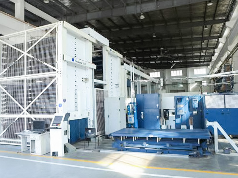
Before bending or forming operations, sheet metal that has developed internal stress patterns from coil storage or prior processing must be leveled to achieve consistent flatness. A leveling machine passes the sheet through a series of alternating upper and lower rolls that progressively work out the internal stress gradients, producing a flat, stress-relieved sheet with consistent material properties across its surface.
Leveling is particularly important for precision bending operations where flatness variation in the blank would translate directly into angular error in the bent component. A sheet with a 2mm bow across its width will produce a bent part with a corresponding angular deviation that may be outside tolerance. For high-precision enclosures, aerospace brackets, and instrumentation panels where dimensional consistency is critical, leveling of the blank before bending is standard practice rather than an optional step.
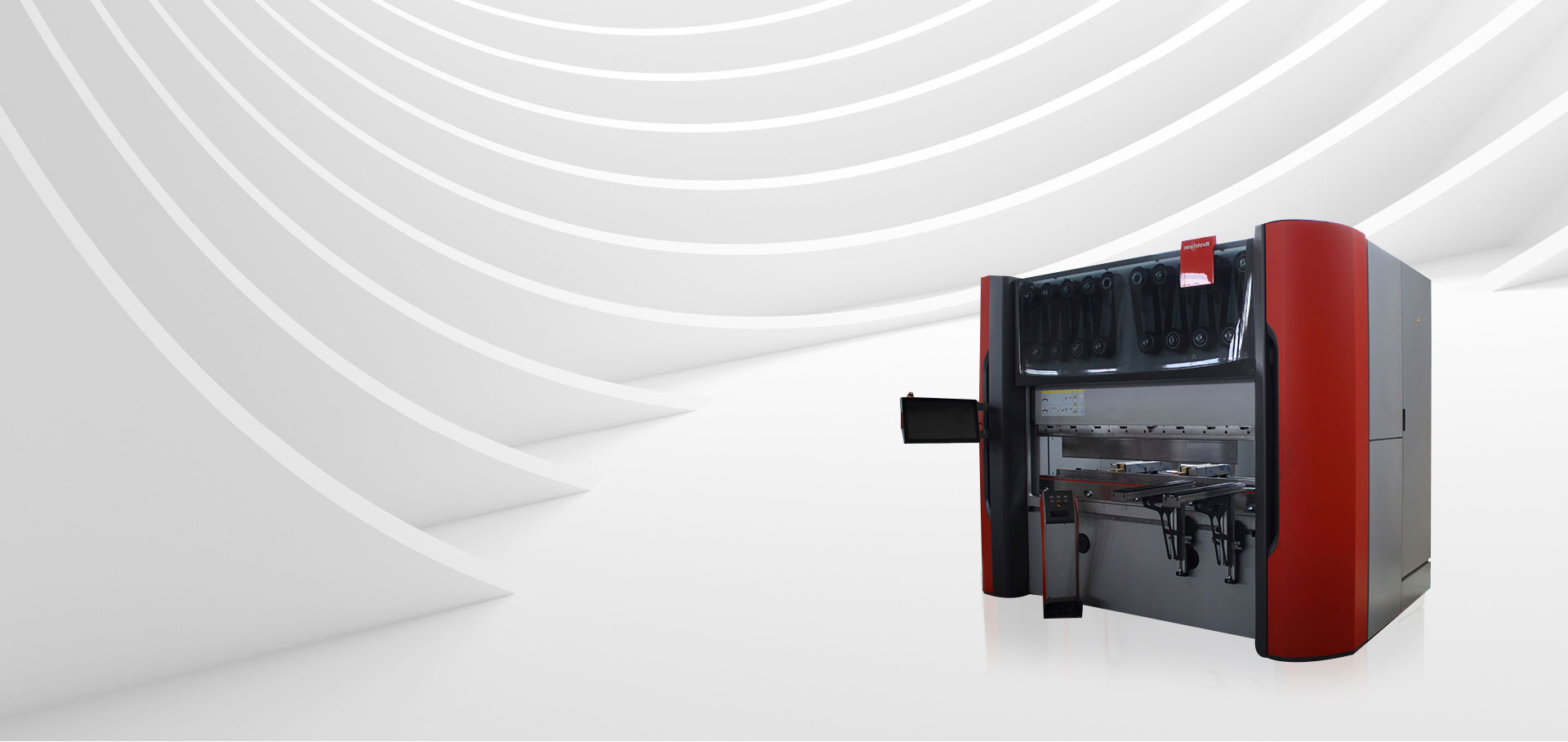
Bending transforms the flat blank into its final 3D profile. A CNC press brake clamps the sheet between a punch tool (upper beam) and a V-die (lower tool) and applies force to bend the sheet to the programmed angle. Modern CNC press brakes use real-time angle measurement sensors and adaptive crowning systems to compensate for machine deflection and material springback, achieving angular accuracy of ±0.1° or better across the full bend length.
The bending sequence — which bend is made first, which last — is critical for complex multi-bend parts. An incorrect sequence can result in the partially-formed part colliding with the press brake tooling during a subsequent bend, making the part impossible to complete. CNC bending programs include bend sequence optimization as part of the programming process, and for new complex parts, a trial bend with a prototype blank before production run is standard practice to verify the sequence and check final dimensions against CAD.
The key material parameter for bending is the minimum bend radius relative to material thickness. Bending too tight a radius on thick or hard material causes cracking on the outer surface of the bend. The minimum inside bend radius for mild steel is typically 1× material thickness; for stainless steel, 1.5–2×; for aluminum, 1–1.5×, depending on alloy and temper. Specifying bend radii below the material's minimum in a part drawing forces the fabricator to either reject the specification or risk part cracking — a common design-for-manufacturability error that review by an experienced fabricator catches early.
Sheet metal components that consist of multiple parts — enclosures, frames, structural assemblies — are joined by welding after bending. The most common welding processes in sheet metal fabrication are MIG (GMAW), TIG (GTAW), and spot welding, each suited to different joint types, material thicknesses, and quality requirements.
MIG welding uses a consumable wire electrode fed continuously through the welding gun and is the standard process for structural sheet metal assembly, where weld speed matters more than cosmetic appearance. TIG welding uses a non-consumable tungsten electrode and produces a cleaner, more controllable weld pool — it is the appropriate process for stainless steel components where weld appearance is important, for thin material where burn-through risk must be minimized, and for aluminum. Spot welding uses electrical resistance at the contact point between two overlapping sheet surfaces to fuse them without filler metal — it is fast and consistent for lap joints in thin sheet, commonly used in automotive and appliance body panel assembly.
Automatic and robotic welding systems increase weld consistency and speed on high-volume repetitive assemblies. For prototype and low-volume custom fabrication, manual TIG and MIG welding by skilled operators remains the most flexible approach. The choice between manual and automated welding should be driven by volume, geometry complexity, and quality requirements rather than default preference.
Press riveting installs threaded fasteners — nuts, studs, standoffs, and panel fasteners — permanently into sheet metal components without welding heat. A hydraulic press riveting machine squeezes the fastener into a pre-punched hole with controlled force, causing the fastener's knurled shank to cold-flow into the sheet material and create a permanent, torque-resistant installation.
Press-installed fasteners (PEM fasteners and equivalent) are standard in sheet metal enclosures, control panels, and electronic equipment housings where threaded connections must be made to thin sheet that cannot be tapped directly for sufficient thread engagement. The advantage of press riveting over weld nuts is process cleanliness — no heat, no weld spatter, no risk of sheet distortion from thermal input — making it the preferred fastener installation method for precision painted or powder-coated components where surface finish must be protected.
Industrial polishing of sheet metal components serves two purposes: surface preparation for subsequent coating processes, and final cosmetic finishing for components that will be left in a bare metal or brushed metal finish. Abrasive belt polishing removes weld marks, scale, scratches, and surface irregularities from fabricated assemblies. Vibratory finishing tumbles components with abrasive media to deburr edges and produce a consistent surface texture across complex geometries.
For stainless steel components intended for food processing, pharmaceutical, or architectural applications where the bare metal surface is the final finish, multi-stage polishing — rough grinding, medium polishing, fine polishing with progressively finer abrasives — produces the brushed, mirror, or electropolished finish specified by the application. The Ra (roughness average) surface finish value should be specified in the drawing when surface finish is a functional requirement, not just an aesthetic one.
The final stage for most structural sheet metal components is surface coating — typically powder coating or liquid spray painting — which provides corrosion protection, UV resistance, and the specified color and texture appearance. Automated spray coating systems use electrostatic application to achieve consistent film thickness across complex geometries, including recessed areas and internal corners that are difficult to coat consistently by manual spraying.
Powder coating — where electrostatically charged dry powder is applied and then cured in an oven at 180–200°C — is the dominant finish for structural sheet metal components in industrial, commercial, and consumer applications. It produces a hard, durable, chemically resistant film in a single coat, with no solvent emissions and minimal waste. Film thickness is typically 60–100 microns, compared to 25–50 microns for a typical liquid primer-plus-topcoat system. For components requiring specific gloss levels, textures (smooth, wrinkle, matte, hammertone), or RAL color matching, powder coating delivers consistent, reproducible results across production batches.
| Capability Area | What to Verify | Why It Matters |
|---|---|---|
| Laser cutting | Laser power (kW), max sheet size, material thickness range | Determines what materials and thicknesses can be processed |
| CNC bending | Press brake tonnage, max bend length, angle accuracy spec | Determines max part size and achievable angular tolerance |
| Welding | Processes available (MIG/TIG/spot), automation capability | Determines joint quality and volume scalability |
| Surface finishing | Coating type, color matching, and film thickness specification | Determines corrosion performance and appearance consistency |
| Quality system | ISO 9001 certification, CMM measurement capability | Determines traceability and dimensional verification rigor |
| In-house process scope | Which stages are in-house vs subcontracted | Subcontracted steps add lead time and quality control gaps |
| Prototype capability | Minimum order quantity, prototype lead time | Determines how quickly design iterations can be validated |
| DFM support | Engineering review of drawings before quote | Catches design errors before tooling and production investment |
The most commonly fabricated sheet metals are mild steel (cold-rolled and hot-rolled), stainless steel (304 and 316 grades for most applications), aluminum (5052 and 6061 alloys are the fabrication standards), galvanized steel, and electrolytic zinc-coated steel (SECC). Copper and brass are fabricated for electrical and decorative applications but require specific tooling and process adjustments due to their different hardness, ductility, and thermal conductivity compared to steel. Material selection affects every stage of the fabrication process — laser cutting parameters, bending radii, welding process, and coating compatibility all change with the base metal — so material specification is the first design decision in any sheet metal component development.
Achievable tolerances depend on the process stage. Laser-cut hole positions and external profiles on thin steel can hold ±0.1–0.15mm with good equipment and programming. Bent dimensions are inherently less precise due to material springback variation: ±0.3–0.5mm on overall length and ±0.1–0.3° on bend angle are typical for production CNC bending. Welded assemblies accumulate tolerances from all parts and joint gaps; weld distortion from heat input adds further variation. For assemblies requiring tight overall dimensional tolerances, designing in adjustment features — slotted holes for positional adjustment, reference datums — is more practical than attempting to hold tight stack-up tolerances through welding alone.
Sheet metal fabrication drawings should include both the flat pattern (developed blank layout showing cut profile and hole positions) and the 3D formed view (showing bend angles, directions, and overall assembly dimensions). Specifying material grade and thickness, minimum bend radii, surface finish (Ra value or coating specification), and any critical dimensions that require inspection is essential. For complex assemblies, a 3D CAD model (STEP format) alongside the 2D drawing allows the fabricator's CNC programming team to work directly from the geometry rather than interpreting 2D projections. Providing a 3D model significantly reduces quoting lead time and the risk of programming errors on complex multi-bend parts.
Prototype lead time for custom sheet metal components is typically 5–15 working days, depending on part complexity and the fabricator's current workload. This covers programming, cutting, bending, welding, finishing, and inspection. Production run lead times for repeat orders with established programs are typically 10–25 working days. Lead time is most heavily influenced by the surface coating stage — powder coating batch cycles and curing time add 3–5 days to most orders — and by the complexity of the welding and assembly stage for multi-part assemblies. Providing complete, accurate drawings at the inquiry stage and approving the quote promptly are the buyer's most effective tools for minimizing lead time, as drawing clarification cycles are the most common source of fabrication delays.
Laser Cutting | Punch Press | Bending Machine | Welding | Press Riveting | Polishing | Leveling | Spray Coating | Custom Services | Contact Us


 +86-13771171111 +86-13338110517

 English
 中文简体
中文简体 日本語
日本語 Deutsch
 Español
 Bahasa Melayu